CMI Tools for Civil 3D
CAD Masters, Inc. (CMI) has created CMI Tools for Civil 3D to enhance the capabilities of Civil 3D. CMI Tools are included as a free benefit for customers who purchase their Autodesk Subscription from CAD Masters. Or it can be purchased for $99/seat.
Below is the documentation for the product with a detailed description of each of the commands and how to use them.

Dview Twist Panel
This panel contains commands to manipulate the dview twist angle of modelspace and/or viewports. Setting the dview twist angle can be difficult to set accurately, these commands will help you with this process.
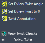
- Set Dview Twist Angle – This command allows the user to enter a value or pick points to define the positive x-axis. It keeps the same zoom value and changes the crosshairs to match the current dview twist angle.
- Set Dview Twist to 0 – Set the dview twist to 0 and the crosshairs back to the current view.
- Twist Annotation – This command rotates AutoCAD text objects to the current dview twist angle, World Coordinate System, or a specific angle.
- View Twist Checker – This simply checks the drawing for current dview twist angle.
Crosshair Angle Tools Panel
This panel supplements the dview twist panel in that it manipulates the crosshair angle independently of the dview twist angle.
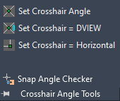
- Set Crosshair Angle – This command changes the angle of the crosshairs in the current drawing based on user input.
- Set Crosshair = DVIEW – This command changes the crosshair angle to the same value as the current DVIEW twist angle.
- Set Crosshair = Horizontal – This command changes the crosshairs to be horizontal in the current view.
- Snap Angle Checker – This lists the current value for the crosshairs.
Point Utilities Panel
This panel contains various commands to manipulate points and create tables with alignment information Civil 3D cannot do out-of-the-box.
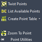
- Twist Points – The command prompts to select AECC_POINTS at then can rotate the marker and point label to the desired angle.
- List Available Points – This command displays the point numbers available in the drawing.
This displays the drop-down menu for the create point table commands.
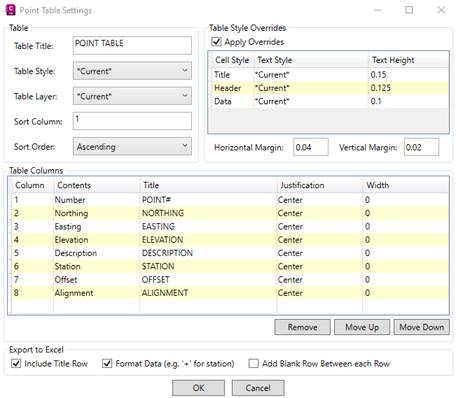
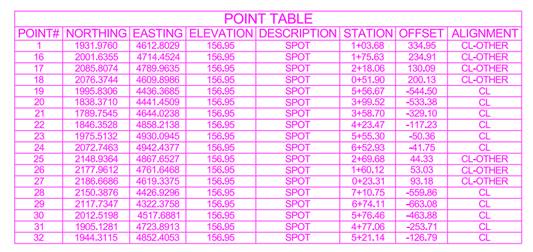
- Create Point Table – This command creates an AutoCAD table based on the settings you provide.
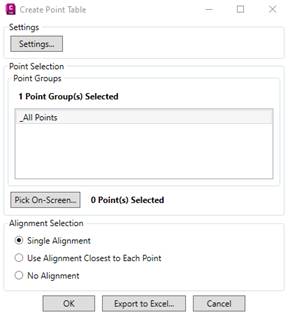
- Update Point Table – This command updates any selected point table with any edits to the points in the table.
- Zoom To Point – A simply function to zoom to any point by typing in the point number.
Alignment Utilities Panel
This panel labels and lists data based on alignment profile elevations. Including setting points based on stationing and design locations for staking.
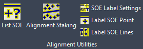
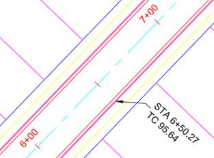
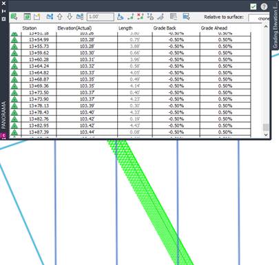
- List SOE – The SOE stands for Station, Offset, Elevation. This command will prompt the user for a station and profile, then select a plan location, the following display will show. It provides a station, offset, elevation, and the instantaneous grade of the profile at the selected plan location.

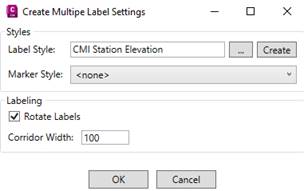
- SOE Label Settings – This determines how the labels will be displayed when labeling off the alignment. Choose the label style to use or use the default label style by clicking the Create button.
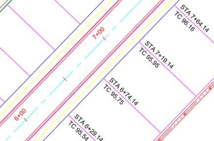
- Label SOE Point – This command will create one label. It will prompt you for a label location and a rotation.
- Label SOE Lines – This command will create labels but selecting AutoCAD linework. The closest vertex to the alignment is the label point and the angle of the line will be the rotation of the label. The corridor width in the settings dialog box determines how far the command will label away from the alignment.
Profile Utilities Panel
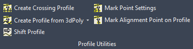
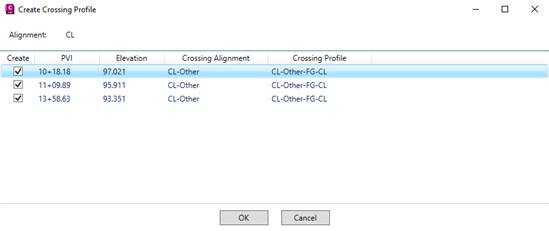
- Create Crossing Profile – This command creates a profile when alignments cross it in at least 2 points.
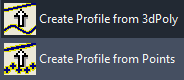
- Create Profile from 3dPolyline/Points – This command will create a profile in an existing alignment using either points or 3D polylines.
- Shift Profile – This command will shift a profile by the chosen distance. This makes it easier to move a finished grade profile when the alignment geometry changes. Select the alignment, then profile. The command with prompt for a distance to shift the profile.
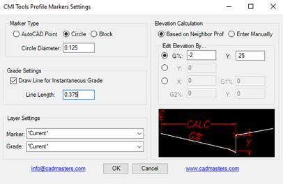
- Mark Point Settings – This displays the settings for marking the profile view with a marker.
- Mark Alignment Point on Profile – This command with mark the select plan point on the profile view of the associated alignment.
Style Utilities Panel
These utilities will perform mass changes in a particular drawing to change Civil 3D styles,
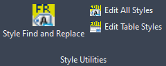
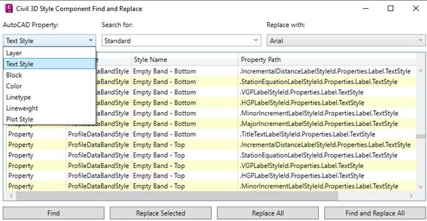
- Styles Find and Replace – This command searches for different AutoCAD properties and replaces the desired value is mass.
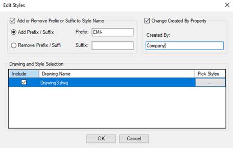
- Edit All Styles – This command can all styles or by selection to add/remove a prefix to the name of styles as well as the created by property.
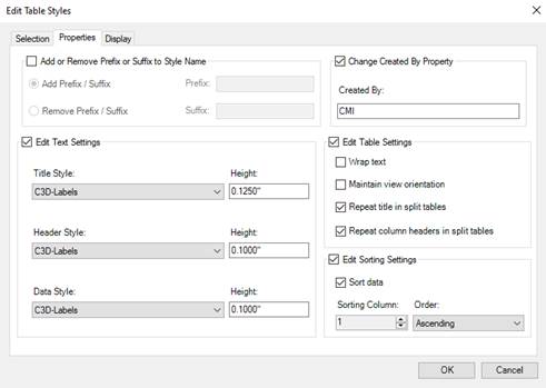
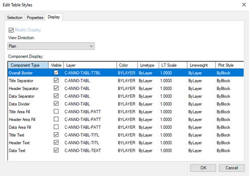
- Edit Table Styles – This command edits properties and display options for the select open drawings and selected styles.
Template Utilities Panel
This panel fills the gap the Civil 3D has for transferring object layers from one drawing to another, as well as description keys and survey figure settings.
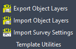
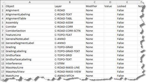
- Export Object Layers – This command exports the current drawings object layer settings to an Excel spreadsheet that can be edited for standard compliancy. Here’s a n example of the format.
- Import Object Layers – This command will import the object layers from a file that was exported previously.
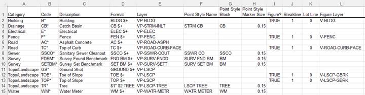
- Import Survey Settings – This command is designed to import description keys and survey figure prefix database from an Excel spreadsheet. Simply edit the example Excel file from the one provided after installation. It can be found in the following location.
%appdata%\Autodesk\ApplicationPlugins\CMIToolsC3D20XX.bundle\Contents\Survey Standards - Sample.xlsx
XX = Version of CMI Tools installed
Corridor Utilities Panel
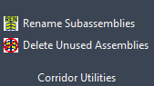
- Rename Subassemblies – This command renames all subassemblies in the drawing based on type, or just the selected assemblies.
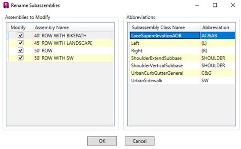
Result
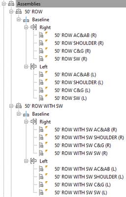
- Delete Unused Assemblies – This command deletes any assemblies in the drawing not used in a corridor.
Other Utilities Panel
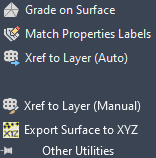
- Grade on Surface – This command creates a feature line that finds the path of a constant grade or slope. The command will prompt the user which direction to go on the surface and it will find that grade or slope along that path as long as it can go.
- Match Properties on Labels – This command with match the dragged state from point, labels, and multi-leader status to multiple objects simultaneously.
- Xref to Layer (Auto) – This command with xref a selected drawing automatically at an insertion point of 0,0,0, zero rotation, and a 1 scale factor. It creates a layer name for the xref to be inserted prefixed with XR and the name of the reference is added to the prefix.
- Xref to Layer (Manual) – The command places an xref on a layer just like the previous command. The difference is this command allows a different insertion point, rotation, and scale.
- Export Surface to XYZ – This command exports a Civil 3D surface to a text file.